ELECTRONICS - [RS-232 Interface] - [page 3/4]
I have implemented a basic communication protocol to communicate with the PIC. The computer will need to send a request frame to the microcontroller. Such request frame must contain 4 or more bytes:
The following image shows a sample request that is transmitted from the PC to the PIC controller. In this example three data bytes are transmitted, to control 24 different outputs. The checksum is 0xF6 (0xF0 + 0x03 + 0x01 + 0x01 + 0x01 = 0xF6. Please notice the modulo 256 operation has no effect here).

The PIC microcontroller will always respond with a single byte. The response can either be 0x0F in case when the command was executed, or 0xF0 when there was a communication problem (wrong packet size, wrong checksum).
As with most of my PIC designs, the software was written in the High-Tech C lite programming environment. You can find the source code at the end of this page.
I used the PIC's built-in USART to receive the serial data. Each time a data byte is received, the interrupt handler will be called. This handler will then add the data to a buffer. I used a pointer to indicate where the next data byte should be stored. By default 20 RAM bytes are reserved to be used for the buffer. Once the buffer is filled completely no more data will be added.
The image below illustrates the buffer that is used to store all received data. After the reception of a byte it is stored in the address that is pointed to by the pointer. Then the pointer is increased to the next address.
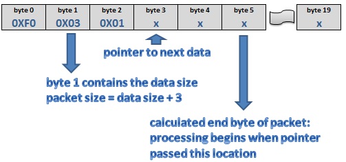
byte 1 contains the number of data bytes that are being used (the number of shift registers in the circuit). The program will use this number to calculate the length of the complete request frame: length = data bytes + 3. (1 start byte + 1 data length byte + 1 checksum byte). The processing of the data will begin as soon as the required number of bytes are received. During this processing the checksum is verified. After a positive verification the bytes will be transmitted to the shift registers, bit by bit.
It could happen the transmission of a request packet gets interrupted. In this case the data inside the buffer will become invalid: the pointer will point to an invalid location. I have used the PIC's timer to prevent this: it will reset/clear the buffer when the data remains there for too long.
Here you can find the High-Tech source code for my project. Please notice the firmware is not confirmed under all circumstances yet. Some bugs might still exist.
![]()
![]()
Copyright ©1998-2022 Vanderhaegen Bart - last modified: August 24, 2013
