ELECTRONICS - [PIC applications]
This page is about an old LM032L LCD module from Hitachi. I found an old one and tried to make it work. The module can display 2 lines with 20 characters each. This page will describe how I got the module to work on a PIC 16F84A microcontroller.

First I had to find the datasheet for the LM032L LCD, which is no big deal when you use Google. The datasheet will show you how to connect the LCD module. It turned out the LM032L has 14 connections: 8 data lines (DB0...DB7), the power supply (Vss,Vdd,Vo) and some additional control lines (RS,RW,E).
So our module uses 8 parallel lines to send data to it. We can also use it with only 4 lines of data, this saves us some I/O lines on the PIC microcontroller. In this 4-bit mode each byte is transmitted in two phases: first the 4 upper bits are transmitted, then the the 4 lower bits. THIS is the approach I will use for my LCD controller: the PIC16F84A only has 13 I/O pins. We can't afford to use 11 of them just to control an LCD module.
The datasheet of the LM032L does not tell us how to control the LCD module. This is because the LM032L uses another chip to do the actual controlling of the LCD module: the HD44780. This HD44780 has its own datasheet and counts no less than 59 pages! The information in this datasheet applies to the LM032L module as well.
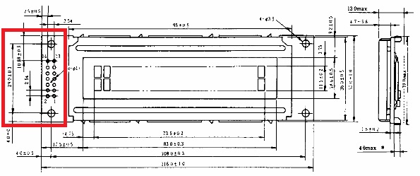
The LM032L module has 14 connections that can be soldered. The connections are not numbered but you can find the numbering in the datasheet of the LM032L. The image is not very clear but at the left of the module there are 14 soldering contacts, formed by 2 vertical rows with 7 connections each. The numbering #1 starts with the right connection of the last row.
| Pin | Vss | Function |
| #1 | Vss | Power Supply 0V |
| #2 | Vdd | Power Supply +5V |
| #3 | Vo | Contrast (0V) |
| #4 | RS | 1=data,0=instruction |
| #5 | RW | 1=read, 0=write |
| #6 | E | 1=enable |
| #7 | DB0 | databus A0 |
| #8 | DB1 | databus A1 |
| #9 | DB2 | databus A2 |
| #10 | DB3 | databus A3 |
| #11 | DB4 | databus A4 |
| #12 | DB5 | databus A5 |
| #13 | DB6 | databus A6 |
| #14 | DB7 | databus A7 |

The used circuit is very easy. It is the basic implementation of the PIC16F84A: the chip is powered by applying 5 VDC between the VDD and VSS pins. The capacitor C3 will filter out the high frequency noise. The PIC is driven by an external 4 MHz crystal. C1 and C2 are needed to work properly.
The LCD module is connected to the connector J2. The PIC's Ports RB7:RB4 will drive the DB data pins. The ports RB3:RB1 will drive E (Enable), RW (Read/Write) and RS (Instruction/Data). The Vo connection, to regulate the contrast of the module, is connected to the GND (fixed contrast).
The circuit should be powered by a 5 VDC stabilized voltage. You need to add a voltage regulator (7805) and some capacitors if you don't have a stabilized voltage.
My software for the PIC is written in High-Tech C Lite (free version). The software will just initialize the LCD and show you the words "Hello World!". My application defines an array of characters containing the String to show on the LCD. A pointer to this array is then passed to the writeString function. This function will transmit the bytes to the LCD module.
Using this program on a 16F84A microcontroller has a huge disadvantage: the limited RAM space of the 16F84, which is only 68 bytes. Each character in the lcd[] character array will use a single byte of RAM. I see a few possibilities to overcome this problem:
I have worked out a sample application that demonstrates how you could use the internal EEPROM to store data. This EEPROM will store 4 different string messages. Each message can contain up to 15 characters (The 16th character should always be 0). In this application you can select a message by applying a 5 VDC voltage to the RA0,RA1,RA2 or RA3 input of the 16F84A (note: I didn't illustrate this in the schematic diagram above).
My program uses the __EEPROM_DATA macro to assign the texts to the EEPROM memory. Please make sure every call to this macro contains 8 parameters. Use NULL (0) values when you don't need any more characters. My PIC firmware will determine the end of a string by scanning for this NULL character.
Here you can download a ZIP containing the High-Tech C source files (for both versions of my firmware) and the data sheets for the LM032L display module.
Copyright ©1998-2022 Vanderhaegen Bart - last modified: August 24, 2013
