Velleman K8055 - [K8055 Hardware Tutorial]
The Velleman K8055 has two analog output channels: they can output a DC voltage between 0 and roughly 5 V. Actually this DC voltage is very weak: you can't use it to drive heavy loads. If the output current gets too high the voltage will start to drop. I am not exaggerating: you can expect a few milliAmps, if you are lucky.
You should use the analog output voltage only as control voltages. An external circuit is required to drive higher currents. One possible circuit is my DAC high power amplifier: I designed it for the DAC outputs of the Velleman K8000. You can control up to 10 Amperes with the circuit.
The microcontroller on the K8055 board had an A/D converter but it doesn't have a D/A converter. The conversion is done by an external circuit that contains some analog components (transistor, resistors, Opamp, ...).
I'll explain in short: the microcontroller will generate a digital PWM signal (Pulse Width Modulation). The frequency of this signal is fixed and very high: about 24 kHz. The microcontroller will control the ratio between the Ton and Toff times, to regulate the average voltage. The higher Ton becomes, the higher the average voltage will be. It is this average voltage that is brought to the analog outputs of the K8055.
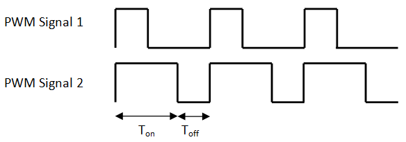
The image above shows two different PWM signals with an equal frequency. In the first graph the Toff > Ton. Its average output is lower than the signal in the second graph.
Now you are maybe wondering: so the analog output signal has a 24 kHz frequency? ... NO! The output has a stable flat DC voltage because the electronics uses a capacitor to filter those frequencies out.
The D/A converter has an output resolution of 8-bit: this means 256 different output voltages are possible. 0 corresponds with the minimal output voltage, while 255 corresponds with the maximal output voltage. Ideally this maximum output voltage would 5 V but it isn't: it is approximately 4.7 V.
I just told the K8055 outputs a flat analog signal. This is not exactly true: it also outputs the PWM signal: a 24 kHz block wave signal where the ratio between the Ton and Toff is controlled by the microcontroller. I actually don't think too many people are using these signals: they are weak (less than 1 V in amplitude) and they aren't clean block waves.
The PWM1/DAC1 or PWM2/DAC2 outputs are always working together since you can't create an analog signal without the PWM signal.
The following demo code assumes you have created a Visual Basic 2010 project with a form, called "Form1". The form doesn't require any components but you do need to add my K8055 class to your project.
    Public Class Form1
      Dim myK8055 As New K8055()
      Dim WithEvents timer As New Windows.Forms.Timer
      Dim daStep As Integer = 5


      Private Sub Form1_Load(ByVal sender As System.Object, ByVal e As System.EventArgs) Handles MyBase.Load
        myK8055.connect(SK5:=False, SK6:=False)
        With timer
        .Enabled = True
        .Interval = 50
        End With
      End Sub


      Private Sub timer_Tick(ByVal sender As Object, ByVal e As System.EventArgs) Handles timer.Tick
        Static counter As Integer

        counter = counter + daStep

        If counter > 255 Then
        counter = 255
        daStep = -System.Math.Abs(daStep)
        End If

        If counter < 0 Then
        counter = 0
        daStep = System.Math.Abs(daStep)
        End If

        myK8055.setAnalogOutputToValue(1, counter)
      End Sub
    End Class
The example will run a dimmer: the output intensity of the LED on the K8055 will slowly increase until the maximal intensity is reached. Then it will start decreasing again. This process is repeated over and over again.
Each cycle the D/A output will increase with a certain number of steps. (This number can be set by setting the daStep variable). During the execution the value of the daStep variable can be +5 or -5. This will indicate if the A/D channel is currently increasing or decreasing. Once the limits are reached (0 or 255), the sign will toggle and the program will change its operation mode (count up/count down).
![]()
![]()
Copyright ©1998-2022 Vanderhaegen Bart - last modified: August 24, 2013
