ELECTRONICS - [Morse Code Typewriter] - [page 3/3]
As you could probably guess, the software part is much more complicated than the hardware part. Basically our PIC's firmware need to do three things:
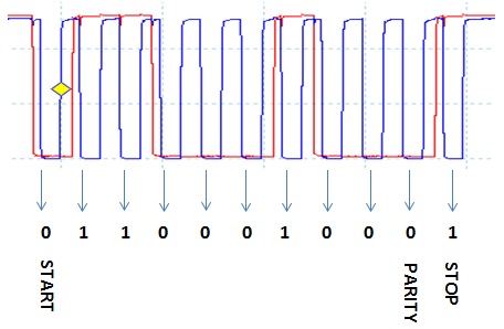
Polling a PS/2 keyboard turned out to be easy: the keyboard generates a clock pulse for each data bit. You can read a data bit when the clock goes from "1" to "0" (falling edge of the clock). 11 databits will form a word, containing: 1 startbit, 8 databits, 1 parity bit and 1 stop bit.
For most ASCII characters a single dataword is transmitted, but for the special characters two data words are transmitted. The keyboard also transmits a "release" code when the key is unpressed. So briefly pressing a key on the keyboard will return 2 words: the keyCode to indicate the key was pressed, and the release code to indicate the key was unpressed again.
The image below shows a typical signal you could measure on an oscilloscope. The blue signal represents the clock, while the red signal represents the data. This signal would decode as the hexadecimal code 0x23. You can verify this yourself: the least significant bit is transmitted first. So our real received data is the binary word 0b00100011, which translates to the hexadecimal 0x23.
The most obvious way to read data from a PS/2 keyboard is to use the external interrupt on the PIC: we can program the PIC microcontroller in a way so it generates an interrupt on the negative edge of the clock pulse (high to low). This way the PIC will never miss a press on the key, even if is currently occupied with something else (like playing the Morse Code).
The PS/2 keyboard clock frequence lies betwien 10 and 16.7 kHz. This is important to know because it's also the frequency of the external triggering on our microcontroller. At 16.7 kHz, an interrupt will be triggered every 59.8 microseconds. This is not a problem for our PIC: it runs on a high 20 MHz clock, 1 instruction cycle will take only 200 nanoseconds. We have plenty of time to execute our interrupt handler.
INFORMATION
The information above is a little bit simplified. A keyboard transmission typical has the following sequence:
It is even more complicated for special keys (like the arrow keys): Here the keyCode is preceded by the code 0xE0. So when releasing such key, three different datawords are transmitted: 0xE0, 0xF0, and the keycode of the key.
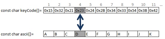
I already told the keyboard transmits key scan codes. They need to be translated to an ASCII code. I did a little trick by defining two different one-dimensional arrays (table) with data. They are called keyCode and ascii.
The keyCode array contains all keyboard codes that can be recognized by the program. During execution the program will search the location of the received keyCode in the table. Let's say the keyboard scanned the code 0x23: This is the fourth position in the keyCode array. Now the program will remember this position (4) and lookup the same position in the ASCII table. There we find the character D. This means the keyCode 0x23 corresponds with the letter D.
Earlier I explained a keyboard can exist in different layouts. A different keyboard layout will require a different keyCode array. Most of the hexadecimal numbers will remain the same, but some will switch place. An example are the codes that correspond with the letters A and Q. I defined 2 keyCode arrays in my PIC's firmware: 1 for AZERTY and 1 for QWERTY. You will need to uncomment the desired array.
The PIC also needs to translate between ASCII characters and Morse code. I have used a method that is similar to the method I just described: the program will search the position of the desired character and look for the corresponding Morse code in a third table.
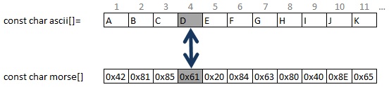
The data inside this table is more complicated. Morse code is a series of 'marks', it can have only 2 possible values: a dot (.) or a dash (-). This is good because we can use the binary format to represent such code. A dot will be represented by the binary "0" while a dash is represented by the binary "1".
The Morse code for our letter D is '-..' (1 dash followed by two dots). We need three bits to represent this number. But the following letter, E, contains only a single dot ('.') so we only need a single bit to represent it: this means the Morse code's characters have a variable length!
So I had to find a way to store the length of each Morse character. A possible solution was to add another data array/table with the length of each character. Unfortunately our PIC doesn't have much space for data storage, this was a no-no. I then found another solution where the length of the Morse character is encoded into the Morse character itself. Let me explain this:
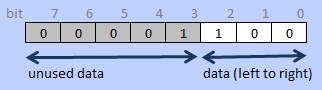
Most Morse characters only contain up to 5 marks (dashes or dots). We need 5 bits to represent such character. Inside the PIC microcontroller eight bits are reserved for each character, so we have 3 unused bits. I used these to encode the length of each character. The following image shows the binary Morse data for the letter D (hexadecimal 0x61).

The bits 5-7 are used to indicate the length of the Morse character: the binary 011 (decimal number 3). They indicate that our Morse character contains 3 marks: bits 0,1 and 2.
INFORMATION
Please note I simplified the information above. It turned out some of the special Morse characters had 6 signs so I had only 2 bits left to encode their length. In these cases I only used 2 bits to indicate the length of the character (bits 6 & 7): a more character has 6 marks when bit 6 & 7 are "1". Now the bit 5 is also used to store a mark.
I used an Excel sheet to calculate the hexadecimal numbers I have put in the Morse[] table. Download the Excel sheet. Warning: it is an Excel sheet with macros (I needed my own custom function to reverse the contents of a cell).
I now realize I have 'overcomplicated' the problem to decode my Morse characters. It was not necessary to encode the length of each character into this data. I could have used a 'start bit': This method uses the binary "1" to indicate the start of the code. The image below will illustrate this: bit 3 contains the startbit. This bit is no part of the Morse code. The Morse code begins right after this bit, only bits 0-2 are used for the actual code.
I won't change my program to implement this method. My program works fine and shows there are often multiple solutions to solve a certain programming problem.
Here you can find the complete firmware for my project. It is written in High-Tech C.
The firmware is currently written for a PS/2 keyboard with an AZERTY layout, but you can easily convert it to a QWERTY layout. Each layout has its own array with keyboard data: const char keyCode[]. You need to comment/delete the version you don't need.
My firmware certainly needs some extra optimisations. Here are some things that still needs to be done:
![]()
![]()
Copyright ©1998-2022 Vanderhaegen Bart - last modified: August 24, 2013
